Monday, September 24, 2012

How Router Interfaces get Their Names on Cisco Routers?

Why is your router’s Ethernet interface called Ethernet0/0 on one router but Ethernet 3/0 on another router? Where do these names come from? This article will explain how Cisco router interfaces get their names.


Where do Router Interfaces get their names?
Router interfaces get their names when the router boots. A “device discovery” takes place and the names of the interfaces are generated based on a predicable method. On fixed interface routers (like the older 2500 series routers) the interfaces will always be the same. However, on newer routers like 2600, 3600, 3700, and 2800 series routers, interfaces can be modular. That means that the interfaces are cards (modules) that can be “plugged into” the router in different slots. Some of these interfaces are on WAN interface cards (WIC) and some are on Network Modules (NM). Other router interfaces will be built right onto the router. The newer model routers have different names for some of these slots like enhanced network modules (NME) and high-speed WIC (HWIC). However, for the purposes of naming the interfaces, the effect is the same.

Interface Naming Conventions
Cisco router interfaces are named with the following convention:
Media-type slot#/port#

The media type is Ethernet, Fast Ethernet, Gigabit Ethernet, Serial, Token-ring, or other media types. You must keep in mind that a 10Mb Ethernet interface is the only kind of Ethernet interface called Ethernet. A 100Mb Ethernet interface is called a Fast Ethernet interface and a   1000Mb Ethernet interface is called a Gigabit Ethernet interface.

Now let’s talk about the “slot#/port#” designation. On the old 2500 series routers, they had fixed ports so there was no slot numbers. Thus, if a 2500 series router had two Ethernet interfaces, they were called Ethernet0 and Ethernet1.  It is important to point out that Cisco slots and ports always start with zero first, then one.

On the newer model routers with slots, any interface built onto the router (a fixed port) is considered to be in slot 0 (zero).  This is even true for WAN interface cards (WIC) slots that are on the router.  Any WIC installed in a router is in slot 0.  So, the first WIC installed in the router will always be WIC 0, even if it is in slot 1. This can be confusing sometimes.  So if Slot 0 has a 2 port serial WIC and Slot 1 had a BRI interface, you have Serial 0/0, Serial 0/1, and BRI0/0.

Say that you have a Cisco 2610 router.  If you put a Serial WIC card in slot zero (called W0 on the router), that module would be called Serial0/0. If there was a two port Serial WIC card in the other slot (slot W1), it would be called Serial0/1 and Serial0/2.

Say that you had a Cisco 3640 router. That router has 4 NM slots and no built in network interfaces. The network module numbering on a 3640 starts with zero and goes to three. This number starts on the bottom right of the router (there are four slots, two and two, each two on top of the other two) with zero. So, the bottom right slot is slot zero. The bottom left slot is one, the top right slot is two, and the top left slot is three. If you put a module with two WIC cards in the top right slot, your WIC cards would be called Ethernet2/0 and Serial2/0.

Here is a picture showing this layout:


The show ip interface brief command is the most useful command to see what interfaces are on the router and what their names are. Here is an example:


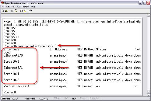
This command output is from a Cisco 2611 router. It has two built in Ethernet interfaces and two WIC slots. In the first WIC slot is a single port Serial module. In the second WIC slot is a two port serial module. You can see how the naming we have been talking about applies to these modules.


If I were to turn off the router, remove the two port serial interface, and reboot the router, you would see that the configuration for those modules has disappeared. Thus, if I were to save that configuration, turn off the router, replace the two port serial module with a good module, and reload the router. The configuration for those two serial modules would be lost. This is another important reason to always have a good backup copy of your Cisco IOS configuration.

Quick overview what you got from the article above:
  • The network interface naming depends on the type of router you have and what slots are on that router.
  • Interface numbering starts at zero and goes up.
  • Router network modules are named zero and go up, starting with the bottom right slot.
  • Be familiar with the models of routers you use and how their slots are laid out.
  • All built in interfaces on a modular router and all WIC cards are considered to be in slot 0.
  • When in doubt, look at the router and how its slots are labeled and do a show ip interface brief to see what slots were found. Preferably, you should match up the physical slots and interfaces with the named interfaces before making any changes on that router.

More Router Tips:

Wednesday, September 19, 2012

Cisco IPv6 Capable Routers


Which routers are IPv6 enabled? Can anybody suggest me any IPv6 enabled routers? (Please give the detailed information, like brand, type etc.)
Alright, Cisco focuses on training, routers, switches, wireless access points, optical networking and information security. As the Internet moves on, more IPv4 addresses become depleted. These 32-bit IP addresses are limited to approximately 4 billion totals. IPv6, a successor to IPv4, resolves the issue by using 128-bit addressing systems. The Internet operates by transferring data between hosts in small packets that are independently routed across networks as specified by an international communications protocol known as the Internet Protocol. This provides plenty of addresses. So many, in fact, that every person alive could be assigned trillions of IP addresses. This different addressing scheme requires routers capable of supporting it.

Cisco makes a number of IPv6 compatible routers for all different budgets.
The Cisco Catalyst 4500 delivers 848 gigabits per second with 48 gigabits per second per slot. It has up to 240 power-providing Ethernet ports that deliver up to 30 watts of power each. It is a foundation model that is the leading seller for large campus networks. The U.S. government has tested the model and certified it as compliant with IPv6 standards.

Notes: More features of Cisco Catalyst 4500 switches
Performance and Density:
848 Gbps fabric with 48 Gbps per slot
Industry’s first enterprise switch delivering up to 60 Watts of PoE power per port with Cisco UPOE
Industry's highest PoE+ port density with up to 240 ports of full 30 Watt PoE+

Application Performance:
Unprecedented layer 2 - 4 application visibility and control with Flexible NetFlow
Only modular access platform that can guarantee Service Level Agreements with IP SLA

Security:
Cisco TrustSec with 802.1ae (MACSec) hop-by-hop encryption and Security Group Tags (hardware-ready)
Anomaly and malware prevention through predefined, policy-based responses with Flexible NetFlow

High Availability:
Protect against attacks with Control Plane Policing
Minimize unplanned downtime with Nonstop Forwarding and Stateful Switchover
Eliminate maintenance downtime with In Service Software Upgrade
Extend power resiliency to a wide range of devices including VDI terminals, IP Turrets, compact switches, personal telepresence systems, and more with Cisco UPOE

Operational Efficiency:
In Service Software Upgrades for industry leading availability
Zero-touch, intelligent provisioning through Auto SmartPorts, AutoInstall and AutoQoS
Comprehensive automation with Cisco IOS Embedded Event Manager
Proactive diagnostics and remediation with Cisco Smart Call Home
Industry-leading power management with Cisco EnergyWise

Cisco ISR 1800
The Cisco Integrated Service Router 1800 is a compact router designed for small offices. It offers wireless capabilities and supports VPN tunneling and power over Ethernet. The device offers Cisco's router security configurations, allowing you to deploy firewall rules over IPv6 specifications. The U.S. government has certified this router as IPv6 capable.

Cisco 7600
Cisco7600 routers provide 720 gigabits per second of transfer. It has a number of adapters and dedicated processors that control audio, video and data quality of service management. Optimized for the high-bandwidth requirements of video-on-demand services, it has features that physically protect your data and network bandwidth from unauthorized access. Designed for service providers, the router is meant to deliver large amounts of information to a diverse pool of clients. The U.S. government has certified this router as IPv6 ready.

Key features & Applications of Cisco 7600VXR
Important Features:
  • High performance, with up to 720 Gbps in a single chassis, or 40 Gbps capacity per slot
  • A choice of form factors purpose-built for high availability
  • Cisco I-Flex design: A portfolio of shared port adapters (SPAs) and SPA interface processors (SIPs) that controls voice, video, and data experiences
  • Scalable and extensible suite of hardware and software capabilities to enable intelligent Carrier Ethernet services
  • Integrated Video Call Admission Control with innovative visual quality of experience for both broadcast and video on demand (VoD)
  • Intelligent Services Gateway, providing scalable subscriber and application awareness with multidimensional identity capabilities and policy controls
  • Integrated Session Border Control with quality of experience in both Session Initiated Protocol (SIP) and non-SIP applications
Applications:
  • Carrier Ethernet: Aggregation of consumer and business service
  • Ethernet services edge: Personalized IP services
  • Wireless mesh networking and mobility service convergence
  • IP/MPLS provider edge routing
  • Enterprise WAN aggregation
  • Headquarters core routing


Monday, September 10, 2012

Set Up IPSec Direct Encapsulation on Cisco Devices


With the importance of internet security being at the forefront of everyone’s mind these days, importance of keeping data safe while in transit is vital. There are of course a number of different technologies that are available to keep data safe including IP Security (IPSec), Generic Routing Encapsulation (GRE), Secure Sockets Layer (SSL) VPNs, and more. One of the major issues that many people have with IPSec is that it does not directly support IP multicast (required for many routing protocols) or protocols other than IP; this is often why a mix of different technologies are used to provide a solution that is optimal for each situation.

For now, let's take a look at just IPSec -- specifically, IPSec direct encapsulation on Cisco devices.

Transport or Tunnel? Tackling IPSec Modes
The first thing to recognize is that IPSec itself is not a protocol but a collection of protocols that are used collectively to create a secure connection between endpoints. While IPSec is an open standard, among the most used features are the Internet Security Association and Key Management Protocol (ISAKMP), which is used to establish a Security Association (SA) between endpoints. This includes a common encryption protocol (for ISAKMP) and authentication method and parameters. Authentication Header (AH) provides the ability for a connection to have integrity protection and data origin authentication, while Encapsulating Security Payload (ESP) provides the ability for a connection to have integrity protection and data origin authentication as well as the ability to have data confidentiality using encryption. IPSec offers two modes of operation: transport and tunnel. The Authentication Header and ESP operate differently depending on the mode being used.

Now that I've thrown a mess of acronyms at you, let's tackle the modes of operation. Intransport mode, AH inserts an IPSec header after the main IP header and is able to protect the contents of all IP header fields. In tunnel mode, AH authenticates the original header, encapsulates it and creates a new IP header which it then protects the same as in transport mode. Because of the way that AH monitors the whole IP header it is not compatible with NAT as NAT changes the source and destination IP address fields.

In transport mode, ESP encrypts the IP payload and inserts an IPSec header after the original header; it does not alter the original IP header and does not authenticate the IP header itself. In tunnel mode, however, ESP inserts the IPSec header after the original IP header, and it encapsulates and encrypts (that is, if configured) the whole IP packet. A new IP header is then put onto the encapsulated packet (this new IP header is not authenticated).

IPSec Direct Encapsulation Configuration
There are a number of commands that are used to set up IPSec. Below, table 1 shows the commands that are required and their options. Obviously, this is certainly a long list of commands to follow. The simplest way to learn it is to set up two routers (or emulated routers) and configure them with these steps.
1
Enter privileged EXEC mode
router>enable
2
Enter device configuration mode
router#configure terminal
3
Create and enter ISAKMP policy configuration mode
router(config)#crypto isakmp policy policy-priority
4
Configure an ISAKMP encryption standard
router(config-isakmp)#encryption [3des |aes des]
5
Configure ISAKMP authentication type
router(config-isakmp)#authentication [pre-share rsa-encr | rsa-sig]
6
Configure a Diffie-Hellman group
router(config-isamkp)#group [2 | 14 |15 16]
7
Exit ISAKMP policy configuration mode
router(config-isakmp)#exit
8
Configure ISAKMP pre-shared key. This is just one method -- other Public Key Infrastructure options can also be used
router(config)#crypto isakmp key key[address ip-address hostname hostname]
9
Configure Dead Peer Detection (DPD) keep alive messages. While this is not required, it provides a mechanism to know when an IKE peer goes down.
router(config)#crypto isakmp keepaliveseconds
10
Create a IPSec transform set. This is a combination of security protocols and algorithms used. There are severaltransforms available; check the Cisco command reference for a complete list.
router(config)#crypto ipsec transform-settransform-set-name transform1 [transform2] [transform3] [transform4]
11
Configure the source IPSec interface to be used
router(config)#crypto map map-name local-address interface
12
Create and enter Crypto map configuration mode
router(config)#crypto map map-name sequence-number ipsec-isakmp
13
Configure the IPSec peer
router(config-crypto-map)#set peer [peer-ip-address | peer-hostname]
14
Configure the IPSec transform set to be used
router(config-crypto-map)#set transform-set transform-set-name
15
 Configure the ACL to be used for interesting traffic. "Interesting traffic" is the traffic that will be acted upon by IPSec
router(config-crypto-map)#match addressacl-number
16
Exit Crypto map configuration mode
router(config-crypto-map)#exit
17
Create an ACL for interesting traffic. This is typically an extended ACL that is used to specify the traffic that will be handled by IPSec.
router(config)#access-list acl-numberpermit ip source-network source-inverse-mask destination-network destination-inverse-mask
18
Enter interface configuration mode. This is the source interface for IPSec
router(config)#interface interface
19
Configure the interface to use a specific crypto map
router(config-if)#crypto map map-name

Far away from the End…
When it comes to IP Security, there are certainly a large number of options and methods of using both IPSec direct encapsulation by itself and in conjunction with other security technologies. Hopefully this article helped make you feel less mired in your understanding of general IPSec concepts, and you've learned a bit about how to how to configure direct IPSec encapsulation without the use of any other technologies.

---Original reference from http://www.petri.co.il/ipsec-direct-encapsulation.htm
Need More Related Tips and Tutorials?
More Cisco and Networking News, Resources, Tips and Tutorials you can visit router-switch.com’s blog

Monday, September 3, 2012

Configuring a Cisco Router as a Frame Relay Switch


A Cisco router now has the capability to simulate a Frame Relay switch. Although this appendix will not show you how configure all of the features that a true Frame Relay switch will have, it will show you how to configure a Cisco router to propagate DLCIs and match them to the appropriate outgoing interfaces to make the router act as a Frame Relay switch.

The most important thing to remember about a Frame Relay switch in the lab is that the DLCI is sent through LMI out a particular interface, and then that DLCI and interface are mapped to an outgoing DLCI and interface.

Physical Connections to the Frame Relay Switch (Cisco 2523)
Before you start configuring the Frame Relay switch, take a look at how the lab routers are connected to the Cisco 2523 acting as the Frame Relay switch. Figure B-7 illustrates the physical connections.


Figure B-7 Frame Relay Physical Connections

As you can see from Figure B-7, R3 will be the "hub" site and requires two PVCs and DLCIs to be configured on interface S0 of the Cisco 2523. R2 and R4 need only one PVC and one DLCI. Begin by configuring the router as a Frame Relay switch.

Table B-1 defines the steps to configuring a Cisco router as a Frame Relay switch.

Table B-1. Configuring a Cisco Router as a Frame Relay Switch
Step
Description
Command
Step 1
Enable Frame Relay switching.
frame-relay switching
Step 2
Configure Frame Relay encapsulation, Frame Relay LMI type, Frame Relay DCE interface mode, and clock rate on individual interfaces.
encapsulation frame-relay frame-relay lmi-type ansi frame-relay intf-type dce clock rate 64000
Step 3
Configure DLCI to interface mappings on individual interfaces.
frame-relay route {local-dlci} interface {outgoing interface and number} {outgoing-dlci}

The first thing is to connect to the Cisco 2523's console port. There is no configuration on the router at this point. You should be in setup mode or at the Router> prompt. If you are in setup mode, just exit this mode (Ctrl-c).

When you are into the router, give it a host name of Frame-Switch.
Router>en
Router#config t
Enter configuration commands, one per line.  End with CNTL/Z.
Router(config)#hostname Frame-Switch

Do not worry about passwords and Telnet connectivity. This router will be a standalone Frame Relay switch. If you need to access it, you will connect to the console port.

Begin with the first step documented in Table B-1, and enable Frame Relay switching on the router. Example B-1 illustrates this configuration step.

Example B-1. Enable Frame Relay Switching
Frame-Switch(config)#frame-relay switching
Frame-Switch(config)#

After the Frame Relay switching process has been started, configure the individual interfaces for the Frame Relay switch. This includes changing the encapsulation type to frame-relay and changing the LMI type to ANSI. Because all interfaces on the Frame Relay switch are DCEs (refer to the Figure B-7), they will need to be changed to the Frame

Relay type DCE and must have the clock rate command issued as well. Example B-2 demonstrates these commands for interface Serial0.

Example B-2. Frame-Relay Commands for Serial0
Frame-Switch(config)#int serial0
Frame-Switch(config-if)#encapsulation frame-relay
Frame-Switch(config-if)#frame-relay lmi-type ansi
Frame-Switch(config-if)#frame-relay intf-type dce
Frame-Switch(config-if)#clock rate 64000

Now that all the Frame Relay commands have been set, you need to map the local DLCI of this interface to the outgoing DLCI and port. Because the Serial0 interface has two PVCs, it needs two mappings. Example B-3 shows the commands.

Example B-3. DLCI-to-Interface Mappings for Serial0
Frame-Switch(config-if)#frame-relay route 100 interface serial 2
      101
Frame-Switch(config-if)#frame-relay route 200 interface serial 1
      201
Frame-Switch(config-if)#no shutdown

From Figure B-7, you know that Serial 0 has two PVCs, one to R2 and one to R4. The first highlighted portion of lines 1 and 2 in Example B-3 point out the local DLCI that will be advertised out Serial 0. Therefore, R3 will see DLCI 100 and DLCI 200 because R3 is connected to the Frame Relay switch on Serial0. The second portion of highlighting in lines 1 and 2 marks the outgoing interface to which each DLCI is mapped. Therefore, anything coming from R3 on DLCI 100 will be sent to Serial2, and anything coming from R3 on DLCI 200 will be sent to Serial1. The last portion of highlighting in lines 1 and 2 indicates the DLCI assigned to the outgoing port. So, anything coming from R3 on DLCI 100 will go out Serial2 to DLCI 101, and anything coming from R3 on DLCI 200 will go out Serial1 to DLCI 201. Don't forget to remove the interfaces from shutdown mode.

The next thing you need to do is perform a similar mapping statement on interfaces Serial1 and Serial2, except that the numbers will be reversed. See Example B-4.

Example B-4. Frame Relay Commands and DLCI-to-Interface Mappings for Serial1
Frame-Switch(config)#interface serial1
Frame-Switch(config-if)#encapsulation frame-relay
Frame-Switch(config-if)#frame-relay lmi-type ansi
Frame-Switch(config-if)#frame-relay intf-type dce
Frame-Switch(config-if)#clock rate 64000
Frame-Switch(config-if)#frame-relay route 201 interface serial 0
      200
Frame-Switch(config-if)#no shutdown

The highlighted portion of the configuration shows the local DLCI (201), the outgoing interface (Serial0), and the outgoing DLCI (200). Next, do the same for interface Serial2. See Example B-5.

Example B-5. Frame-Relay Commands and DLCI-to-Interface Mappings on Serial2
Frame-Switch(config)#interface serial2
Frame-Switch(config-if)#encapsulation frame-relay
Frame-Switch(config-if)#frame-relay lmi-type ansi
Frame-Switch(config-if)#frame intf-type dce
Frame-Switch(config-if)#clock rate 64000
Frame-Switch(config-if)#frame-relay route 101 interface serial 0
      100
Frame-Switch(config-if)#no shut
Frame-Switch(config-if)#

The highlighted portion of the configuration shows the local DLCI (101), the outgoing interface (Serial0), and the outgoing DLCI (100). At this point, you have a functional Frame Relay switch. You will be able to verify the connections in Chapter 7, "Router Interface Configuration," but for now, take a look at the configuration and do a show frame-relay route to verify that the configuration matches the lab diagram. Example B-6 shows the running-config file. Notice where the commands are located in the configuration file.

Example B-6. Output from show running-config
Frame-Switch#show running-config
Building configuration...

Current configuration:
!
version 11.2
no service password-encryption
no service udp-small-servers
no service tcp-small-servers
!
hostname Frame-Switch
!
!
frame-relay switching
!
interface Serial0
 no ip address
 encapsulation frame-relay
 clockrate 64000
 frame-relay lmi-type ansi
 frame-relay intf-type dce
 frame-relay route 100 interface serial2 101
 frame-relay route 200 interface Serial1 201
!
interface Serial1
 no ip address
 encapsulation frame-relay
 clockrate 64000
 frame-relay lmi-type ansi
 frame-relay intf-type dce
 frame-relay route 201 interface Serial0 200
!
interface Serial2
 no ip address
 encapsulation frame-relay
 clockrate 64000
 frame-relay lmi-type ansi
 frame-relay intf-type dce
 frame-relay route 101 interface Serial0 100
!
interface Serial3
 no ip address
 shutdown
!
interface Serial4
 no ip address
 shutdown
!
interface Serial5
 no ip address
 shutdown
!
interface Serial6
 no ip address
 shutdown
!
interface Serial7
 no ip address
 shutdown
!
interface Serial8
 no ip address
 shutdown
!
interface Serial9
 no ip address
 shutdown
!
interface TokenRing0
 no ip address
 shutdown
!
interface BRI0
 no ip address
 shutdown
!
no ip classless
!
!
line con 0
 exec-timeout 0 0
line aux 0
line vty 0 4
 login
!
end

Frame-Switch#
The highlighted portions illustrate all the Frame Relay configuration tasks that you completed. Notice that none of the interfaces has IP addresses, nor do any of the interfaces need them. You are only mapping DLCIs to interfaces. This is a Layer 2 function, not a Layer 3 function, therefore, no IP address are needed.

The show frame-relay route command is a useful command in determining that your configuration is correct. Example B-7 shows the output from this command.

Example B-7. Output from show frame-relay route Command
Frame-Switch#show frame-relay route
Input Intf      Input Dlci      Output Intf     Output Dlci     Status
Serial0         100             Serial2         101             inactive
Serial0         200             Serial1         201             inactive
Serial1         201             Serial0         200             inactive
Serial2         101             Serial0         100             inactive
Frame-Switch#

From this output, you can see that the Input Dlci matches the correct interfaces from the lab diagram in Figure B-7. You also can see that Output Intf and Output Dlci match to the correct interfaces and DLCIs as well. From here, you can assume that everything is configured correctly. The status will be inactive until you configure the Frame Relay interfaces on R2, R3, and R4 and remove them from shutdown mode.

---Original reading from informit.com
More Related Cisco Network Tips: